The analysis of complex microwave circuits can be efficiently accomplished by a segmentation procedure. The circuit is first decomposed into subsections analyzed individually, and the results are recombined to obtain the overall behaviour of the structure under investigation. For some of the subsections a simple equivalent circuit can suffice while for others a full wave analysis is required. In order to create a link between these different techniques one can perform a full wave analysis of complex components and extract an equivalent lumped element circuit from such analysis. This work deals with the extraction of equivalent circuits from a complex component pre-simulated with the TLM method. The equivalent circuit is extracted with a rigorous procedure leading to the topology and the value of its elements. The procedure can be applied to link time domain field solvers with SPICE type simulators and to create a library of microwave components simulated with TLM for later use. In addition the procedure is extended to include losses for two-port components by including appropriate resistors in the equivalent circuit.
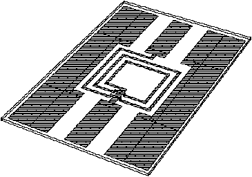
As an example the extraction of the equivalent circuit of a MMIC spiral inductor realized in coplanar technology (Fig. 1) is demonstrated.
From the time domain simulation of the coplanar spiral inductor, the frequency domain admittance Y(p) is computed via Laplace transform.
![]()
In case of low-loss components the Fourier transform can also be adopted since the real part of the poles is relatively small as compared to their imaginary part, and it can be determined solely from their dependance on frequency. The complex admittance matrix is then expanded in a series of poles alpha_n and their residues A_n. By restricting the analysis to a finite range of frequencies the sum can be terminated after a finite number, N, of poles.

The frequency domain Prony's method is used to locate the poles and the corresponding residues. From the pole location and residue values, a canonical Foster realization follows.
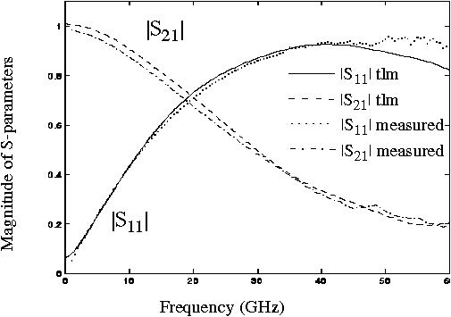
The coplanar inductor has been discretized with a uniform mesh of size 2 micrometres, and the mesh has been excited with a Gaussian pulse covering the frequency range of interest. The S-parameters computed are shown in Fig. 1 and compared with measured results. The agreement between simulated and measured results is excellent in this frequency range, and wideband lumped element extraction can then be performed based on the simulated results.
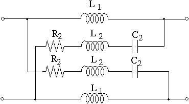
The final equivalent circuit for the coplanar inductor, after simplifying and neglecting the non-relevant elements, is shown in Fig. 2. Poles for Y11 and Y12 in the frequency range dc-80 GHz and the corresponding lumped element values are shown in the table.
| Pole no. | Freq. (GHz) | Damping factor | Li (pH) | Ri (ohm) | Ci (pF) |
|---|---|---|---|---|---|
| 1 | 0.0 | -3.16 | 9.2 | - | - |
| 2 | 70.73 | -24.16 | 7.9 | 0.38 | 0.644 |
Further details can be found in:
M. Righi, W. J. R. Hoefer, B. Bader, R. Doerner and P. Russer, "Extraction of Equivalent Circuit of MMIC components via TLM Simulation" to be presented at the 1995 MIOP conference Germany.

Geometry of the coplanar spiral inductor: central conductor width: 38 micrometres, ground to ground width: 102 micrometres, air bridge height: 2 micrometres, spiral line width: 4 micrometres, substrate permittivity: epsilon_r=12.9.

Fig. 1 - Magnitude of S-parameters of the open coplanar spiral inductor

Fig. 2 - Equivalent circuit of the coplanar spiral inductor