The two major advantages of time domain numerical methods such as the Transmission Line Matrix (TLM) method is the ability to analyze complex structures with arbitrary geometry, and obtain the frequency characteristics over a wide frequency spectrum with a single time domain simulation. One of the major requirements of time domain methods is the availability of good quality broadband matched loads or absorbing boundary conditions in order to truncate the computational domain. Higher-order absorbing boundary operators may be used to increase the bandwidth of absorption, but long time stability may be difficult to achieve. To overcome this problem, we have proposed an attractive alternative to compute the scattering parameters via admittance parameters.
Computation of admittance parameters does not require matched loads (or absorbing boundary conditions). Therefore, unconditional stability is achieved since exact boundary conditions are imposed. Impulsive voltage excitation and short circuit conditions at the ports enable the computation of admittance parameters directly in the time domain. The procedure is particularly suitable for highly dispersive and lossy components, where high quality ABCs are difficult to achieve and natural decay of the impulse response reduces the computational time.
Once a one-port linear circuit is excited with a voltage source v(t), the response current i(t) can be obtained by convolving the voltage source v(t) and the input admittance y(t):
![]()
If v(t) is an impulse excitation, the current i(t) at the same port becomes equal to the input admittance of the circuit. This procedure can be easily extended to multiport circuits by applying a multiport version of the previous equation. The frequency domain scattering parameters are then easily obtained by standard transformations.
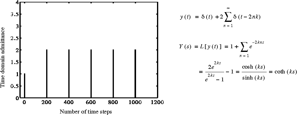
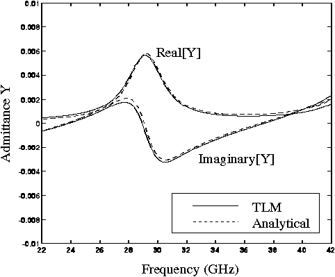
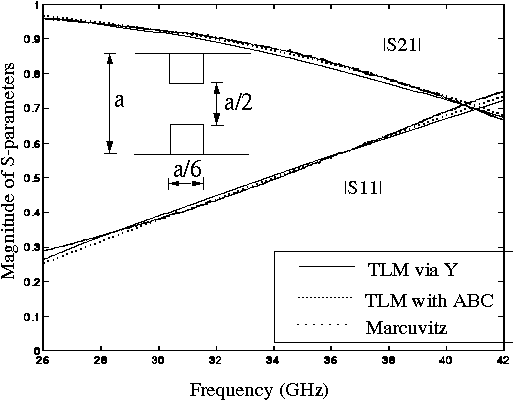
The above procedure has been implemented for the 3D-symmetrical condensed node (SCN) TLM algorithm and used to analyze one- and two-port waveguide components. First, to validate the procedure, we have analyzed a TEM waveguide stub of length 50 dl. The simulated time domain admittance can be represented by the series in Fig. 1 (where delta(t) represents a Dirac delta function and k=100 dt) so that the Laplace transform can be analytically performed. The admittance obtained, Y(s)=coth(ks), is the analytical input admittance of the stub. Having verified the procedure in case of a plane wave stub, we have applied it to a WR-28 waveguide lossy stub (loss tangent of the medium tan delta = 0.1). The impulsive excitation was spatially distributed according to the dominant mode field distribution. Because the response current obtained is an infinite series, windowing of the series must be done in order to reduce the truncation error in the Fourier transform performed on a finite number of time steps. The real and the imaginary part of the admittance have been compared with analytical results in Fig. 2. They agree well in the entire operating range of the waveguide. Finally, a two-port circuit has been considered. A thick inductive iris with aperture a/2 and thickness a/6 in a WR-28 waveguide has been analyzed. Its S-parameters have been computed with three different methods via admittance parameters (SBC), via direct computation using matched loads (ABC) and via Marcuvitz's equivalent circuit model. A comparison of the S-parameter results is shown in Fig. 3.
Further details can be found in:
M. Righi, C. Eswarappa, W. J. R. Hoefer, P. Russer, "An Alternative Way of Computing S-parameters via Impulsive TLM analysis without Using Absorbing Boundary Conditions" to be presented at the 1995 Intl. Microwave Symposium MTT-S, Orlando Florida.

Fig. 1 - Time domain admittance and its representation in the time and in the complex frequency domain

Fig. 2 - Comparison of the analytical and TLM input admittance for a lossy waveguide stub

Fig. 3 - Comparison of S-parameters for a thick inductive iris in a WR 28 waveguide computed via admittance parameters, with ABC and Marcuvitz equivalent circuit