A state-of-the-art electromagnetic wave simulator based on this method has been implemented. This simulator incorporates all the advanced TLM concepts and procedures described in [1] and [2] using the object-oriented programming paradigm [3]. The connections between the graphical interface and the numerical computation modules are carefully designed so that other compatible numerical methods such as finite difference time domain (FD-TD), finite difference (FD) and finite elements (FE) methods can be easily integrated into this simulator. The TLM simulator contains both shunt and series node algorithms.
This simulator is based on a document-view programming model [4]. The document part of the model contains C++ objects which encapsulate the data and procedures of the shunt and series two-dimensional TLM methods. The view part of the model contains various C++ graphical interface objects to display the geometry of the structure under study as well as its responses to the applied electromagnetic excitations. Because of this clean separation between the document and its associated views, compatible numerical methods can be easily integrated into the document object, hence into this simulator, by simply deriving new methods from a common base method. This idea is depicted in Figure 1.
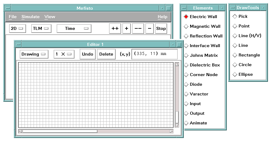
The graphical interface front end of this simulator consists of a main window and five types of subwindows (each subwindow has an associated view object): Editor, Generator, Analyzer, Animator and Johns Matrix, Figure 2 depicts the main control window together with the editor and its associated tool boxes. The main window has a menu system and a button bar which allow users to enter commonly used commands. The other subwindows mimic various kinds of instruments that microwave engineers would normally find in their laboratories, such as drafting table, generator, scope and network analyzer, as well as a hard-to-find instrument - the field animator.
The Editor window, mimics the drafting table, allows users to input the geometry of the structure to be studied via a mouse based user friendly drawing mechanism. The tool boxes on the right of the Editor window allow users to select the desired drawing element. Once the geometry is entered, the Editor can discretize the structure to various degrees of coarseness as specified by users. This feature allows problems to be solved with successively finer meshes, and the results can be used in the Richardson extrapolation procedure [5] to estimate the result one would obtain from an infinitely fine mesh.
The Generator window models the signal generator one would find in the microwave laboratory. It allows users to specify the characteristics of the excitation waveform. The Analyzer window models the oscilloscope. It lets users measure the electrical response of the structure. The Animator window (there is nothing like it in the microwave laboratory) allows users to visualize the field evolution in the structure to be studied; it thus enriches the user's perception of electromagnetic wave propagation to an extent rarely achieved by any other tool in the microwave laboratory. The Johns-Matrix window models a high quality matched load. It lets users terminate the structure to be studied with a minimum reflection at the input and output planes. These windows are shown in Figure 3.
Figure 4 depicts the topology of a microstrip low-pass filter modelled by its equivalent parallel plate waveguide model with non-dispersive effective permittivity. This model is, of course, quite limited but works well at "low" frequencies, in this case several GHz. The input and output ends of the filter are matched. A small reference section with the same electrical properties as the input end is needed for the direct extraction of the S-parameters of the filter, [1] and [2]. The time and frequency domain responses due to an impulse excitation are shown in the same figure as well.
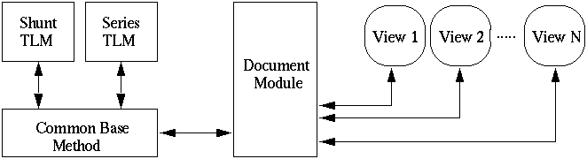
Fig. 1 - The document-view programming model used to implement this simulator. The document module isolates the base numerical method from the various graphical view modules. Therefore, compatible numerical methods can be easily incorporated into the simulator.
Fig. 2 - The graphical front end of the simulator. The tool boxes on the right of the Editor window allows the user to select the desired drawing element.
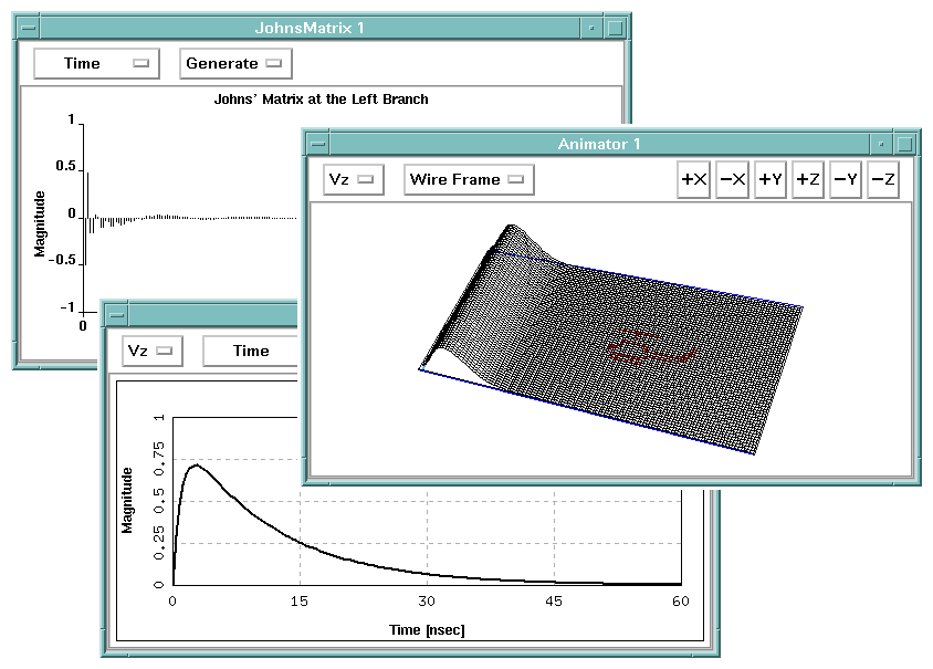
Fig. 3 - The Animator, Generator and Johns-Matrix windows of the simulator. These windows allow users to interactively control the input and output characteristics.
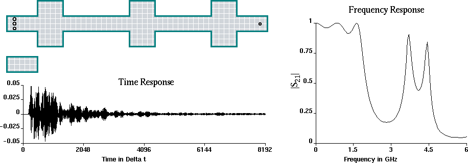
Fig. 4 - The equivalent two-dimensional TLM model of a microstrip low-pass filter, (epsilon_r=9.60, epsilon_eff=8.22, dl=1mm) [1]. The input and output ports are at the left and right sides of the filter, respectively.