Qi Zhang, Jifu Huang, Ke Wu and Wolfgang J.R. Hoefer
Among the critical issues regarding the accuracy of TLM results are the errors due to frequency and directional dispersion in the discrete spatial TLM network. It is well known that the TLM method has a cutoff frequency and deviations from the linear dispersion relation for frequencies approaching the cutoff frequency. This error is produced by the space discretization. In order to evaluate the accuracy of the TLM method and quantify the dispersion error, the dispersion relation of the discrete mesh must be known. The generalized dispersion analysis of two- and three-dimensional TLM schemes was first proposed by Nielsen and Hoefer in 1993 [1]. The usual approach for the derivation of the TLM dispersion relation is based on Floquet's theorem [2] and the network structure. Further work on the dispersion behavior of isotropic media modeled by condensed nodes has been reported by Krumpholz and Russer [3] and Trenkic et al. [4]. The dispersion in anisotropic media has been studied by Huber et al. [5] and Trenkic [6], but the investigations are restricted to wave propagation along the mesh axes and the mesh diagonals in symmetric anisotropic media.
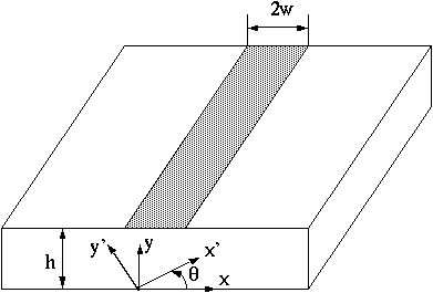
Recently, Huang and Wu have proposed a unified TLM model for wave propagation in electrical and optical structures considering permittivity and permeability tensors [7]. Using this model a TLM algorithm has been derived to address various computational issues in non-diagonal tensor problems encountered in practical situations. However, the wave properties of the node employed in this model have not been systematically investigated yet. The study of the dispersion characteristics of this node remains a great challenge because of the complexity and size of calculations involved. In the project the dispersion analysis is based on the numerical solution of an eigenvalue equation to overcome this difficulty. The dispersion relation for the three-dimensional TLM condensed node modeling arbitrary permittivity and permeability tensors is obtained (Fig.3 - Fig.8). In the analysis, the dispersive behavior of the TLM node modeling m-cut sapphire (Fig.1), r-cut sapphire substrates (Fig.2) and gyromagnetic material is investigated with the same spatial discretization. It is verified that a relatively fine mesh is required to obtain good accuracy in the simulation of the m-cut sapphire material. This analysis shows that it is possible to minimize the numerical dispersion error when modeling anisotropic and gyromagnetic media.
References:

Fig. 1 - Microstrip geometry showing the crystal (x',y') and microstrip (x,y) axes. (m-cut sapphire)
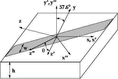
Fig. 2 - Arbitrarily oriented r-cut sapphire-based microstrip.
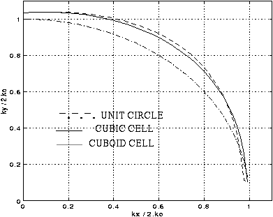
Fig. 3 - The dispersion characteristics for a 3D condensed node in x-y plane. delta_x = 0.2, delta_y = delta_z = 0.1 (sapphire-m-cut, theta= 60 deg)
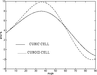
Fig. 4 - The dispersion error for a 3D condensed node in x-y plane. delta_x = 0.2, delta_y = delta_z = 0.1 (sapphire-m-cut, theta= 60 deg)
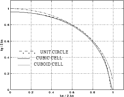
Fig. 5 - The dispersion characteristics for a 3D condensed node in x-y plane. delta_x = 0.2, delta_y = delta_z = 0.1 (sapphire-r-cut)
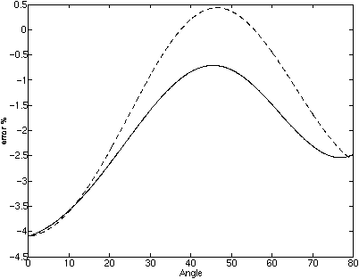
Fig. 6 - The dispersion error for a 3D condensed node in x-y plane. delta_x = 0.2, delta_y = delta_z = 0.1 (sapphire-r-cut, theta= 57.6 deg)
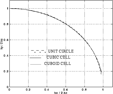
Fig. 7 - The dispersion characteristics for a 3D condensed node in x-y plane. delta_x = 0.2, delta_y = delta_z = 0.1 (gyromagnetic material)
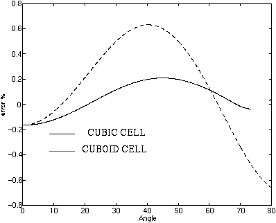
Fig. 8 - The dispersion error for a 3D condensed node in x-y plane. delta_x = 0.2, delta_y = delta_z = 0.1 (gyromagnetic material)